
How to Solder USB Connector to LED Light? Exact Answer & Guideline
How to solder USB connector to LED light? Strip the USB cable to reveal red (5V) and black (GND) wires. Solder red to the LED’s positive terminal and black to the negative. Use flux and a fine-tip soldering iron for precision. Insulate connections with heat shrink tubing. Plug into USB power to test. USB connectors…
How to solder USB connector to LED light? Strip the USB cable to reveal red (5V) and black (GND) wires. Solder red to the LED’s positive terminal and black to the negative. Use flux and a fine-tip soldering iron for precision. Insulate connections with heat shrink tubing. Plug into USB power to test.
USB connectors come in various shapes and sizes, each with its own specifications. The most common types are Micro-USB, Mini-USB, and USB Type-A and Type-C. Choosing the correct connector is crucial for compatibility with your power source and device. For this project, a Micro-USB or Mini-USB connector is often suitable due to their size and ease of handling.
How to Solder USB Connector to LED Light?
To solder a USB connector to an LED light, strip the USB cable to expose the red (positive) and black (negative) wires. Solder the red wire to the LED’s positive terminal and the black wire to the negative. Secure the joints with heat shrink tubing or electrical tape for safety.
Understanding LED Lights
LED Specifications
LEDs (Light Emitting Diodes) have specific voltage and current requirements. Exceeding these limits can damage the LED. You need to know the forward voltage (Vf) and forward current (If) of your LED to choose the appropriate resistor and power source. Typical values for common LEDs range from 2-3.5V and 10-20mA. Incorrect values can lead to LED failure or insufficient brightness.
Read More: 12 Excellent Half Vaulted Ceiling Lighting Ideas
Choosing the Right Components
Selecting Resistors
A resistor limits the current flowing to the LED, preventing damage. Ohm’s Law (V=IR) helps calculate the required resistance. For example, if your LED has a Vf of 3V and your power source is 5V, the voltage drop across the resistor is 2V (5V – 3V). If the LED’s If is 20mA (0.02A), the resistance needed is R = V/I = 2V / 0.02A = 100 ohms. Always use a resistor with a higher wattage rating for safety.
Preparing for Soldering
Gathering Your Tools
You’ll need a soldering iron (with a fine tip), solder (rosin-core is recommended), solder wick (for removing excess solder), wire strippers/cutters, and a suitable work surface (heat-resistant mat). Safety glasses are essential to protect your eyes from solder splatters.
Soldering the USB Connector
Connecting the Positive and Negative Leads
The USB connector typically has a positive (+) and a negative (-) lead. These need to be connected correctly to the LED and resistor. Identify the positive and negative pins on the connector (usually indicated by markings or a schematic) and carefully solder the positive lead to the positive leg of the LED and the negative lead to the negative leg of the LED (via the resistor). Ensure proper connections to avoid short circuits.
Read More: Do LED Lights Cause Cal-Mag Deficiency? A Complete Discussion
Adding the Resistor
Integrating the Resistor in the Circuit
The resistor must be placed in series with the LED on the negative lead. This limits the current to protect the LED. Poor placement could lead to overheating or LED failure. It’s crucial to follow the correct polarity (positive and negative) while connecting the LED and resistor.
Testing Your Creation
Checking for Functionality
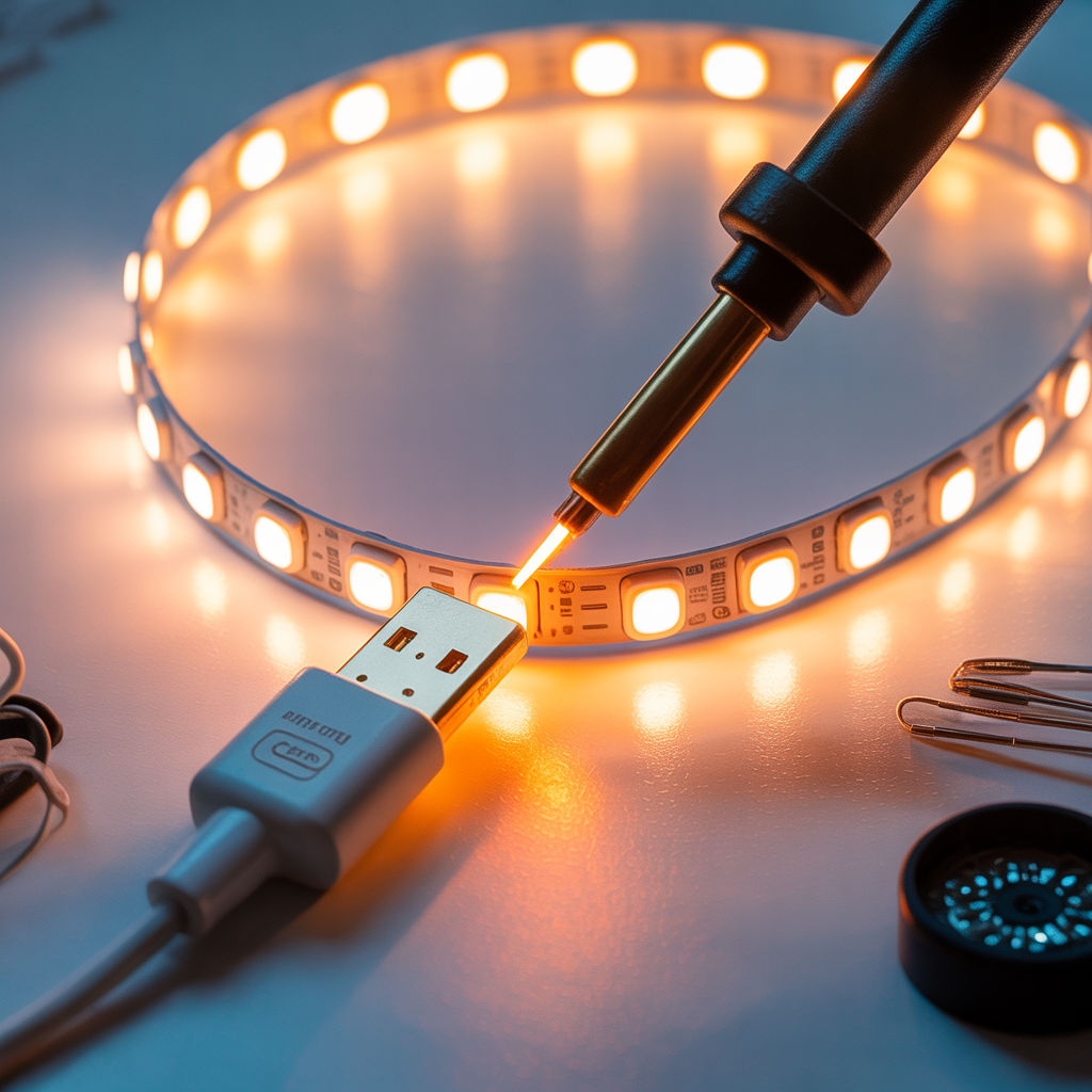
After soldering, carefully plug in the USB connector to a powered USB port. If everything is wired correctly, the LED should light up. If it doesn’t, double-check all connections, ensuring proper polarity and that the LED is not faulty.
Troubleshooting Common Issues
Identifying and Fixing Problems
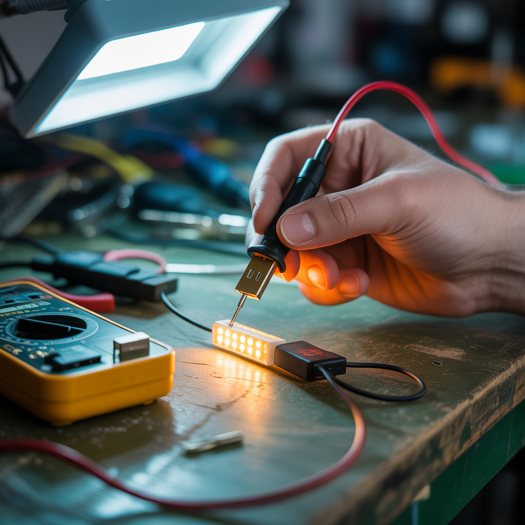
If your LED doesn’t light up, troubleshoot by carefully inspecting each solder joint for cold solder joints (weak connections) or shorts. Use a multimeter to check the voltage across the LED and the resistor to determine if the circuit is working correctly. A short circuit could be caused by solder bridging two leads. If the LED is very dim, it might be due to an incorrect resistor value.
Different Types of LED Lights
High-Brightness LEDs vs. Standard LEDs
High-brightness LEDs require more careful consideration of current limiting, as they can draw significantly more current than standard LEDs. Always check the LED’s datasheet for accurate specifications before calculating resistor values. Using an incorrect resistor with a high-brightness LED can easily burn it out.
Safety Precautions
Protecting Yourself During Soldering
Always use safety glasses when soldering to protect your eyes from potential solder splatters. Ensure proper ventilation, as soldering fumes can be harmful. Avoid touching the soldering iron’s hot tip, and allow components to cool before handling.
Alternative Power Sources
Using Batteries Instead of USB
While this guide focuses on USB power, you can adapt the process to use a battery instead. However, you’ll need to carefully select a battery with appropriate voltage and capacity. You’ll also need a suitable battery connector and may need additional components for voltage regulation.
Advanced Techniques
Using a Breadboard for Prototyping
For beginners, it’s recommended to prototype on a breadboard first before soldering. This allows you to easily test the circuit and make changes without damaging components. Breadboards provide a safe and simple way to experiment with different configurations.
Encapsulation and Protection
Protecting the Soldering Joints
Once your circuit is working, you might consider encapsulating the soldering joints with a suitable protective material (like heat-shrink tubing) to protect them from damage and moisture. This improves durability and longevity.
Working with Different USB Cables
Compatibility with Various Devices
Not all USB cables are created equal. Some offer different power output capabilities. While many USB ports provide sufficient power for low-power LEDs, more power-hungry LEDs might need a different power source or a higher current USB port.
Choosing the Right Soldering Iron
Selecting a Suitable Soldering Iron for the Task
The soldering iron’s wattage and tip size significantly impact the soldering process. A lower-wattage iron with a fine tip is generally preferable for delicate work, like soldering small components to the USB connector. Higher-wattage irons can be less precise.
Using Solder Flux
Improving Solderability with Flux
Solder flux helps improve the flow of solder and makes the soldering process easier and more reliable. It cleans the surfaces to be soldered, allowing for better adhesion of the solder. Always use rosin-core solder, which contains flux within the solder itself.
Frequently Asked Questions
What type of solder is best for this project?
Rosin-core solder is ideal for electronics projects due to its clean nature and relatively low residue. Avoid acid-core solder, as it can damage components.
What if my LED doesn’t light up?
Check the following: correct polarity of the LED and the USB connector, correct resistor value, good solder joints (no cold solder joints or shorts), and a properly functioning USB port. Use a multimeter to check voltage and current in different parts of the circuit.
Can I use any type of USB connector?
While many work, the connector’s pinout must match the voltage and current requirements of your LED and power source. Some connectors provide different power output capabilities. Consider the size of the connector relative to the size of your LED assembly.
What happens if I use the wrong resistor?
Using a resistor with too little resistance can result in excessive current flowing to the LED, causing it to burn out quickly. A resistor with too much resistance will result in a dim or non-illuminated LED.
How can I prevent short circuits?
Carefully inspect your work for solder bridges (accidental connections between leads). Ensure sufficient spacing between components to avoid accidental shorts. Using a breadboard for prototyping can help prevent shorts during experimentation.
Final Thoughts
Soldering a USB connector to an LED light is a rewarding project that lets you understand basic electronics principles and practical skills. By following this guide and taking necessary precautions, you can successfully build a functional and reliable circuit. Remember to always double-check your connections, use the correct components, and practice safe soldering techniques. With patience and attention to detail, you can achieve a well-functioning LED light powered by a USB connector. Whether you’re a beginner or experienced, this comprehensive guide provides a solid foundation for success in this small electronics project. Remember to always prioritize safety and take your time to ensure a clean, reliable connection. Happy soldering!